UPS, BESS & Substations · Lead Times
12–16 weeks production lead time, plus 4–8 weeks for shipping.
Expediting options are available. Contact us to discuss your project schedule.
The repeatable pair
Two batteries. One substation. One unit of scale.
The substation is where storage meets the medium-voltage network. Pair it with two BESS containers and you have 5 MW / 10 MWh — roughly 2 hours nominal at full power before losses and operating limits, not a guaranteed usable runtime.
Why a substation is its own product
Containerized
Housed in a 40-ft container so medium-voltage equipment arrives as a defined, transportable unit rather than a field-built yard.
34.5 kV collection
Rated 5 MW at 34.5 kV. Each unit connects two 2.5 MW BESS containers onto the site medium-voltage system.
Repeatable block
One substation plus two BESS units forms a 5 MW / 10 MWh pair. Repeat blocks to build capacity, with site-level engineering and interconnection review.
Planned logistics
12–16 weeks production lead time, plus 4–8 weeks for shipping. Expediting options are available. Contact us to discuss your project schedule.
Stated parameters
- Rating
- 5 MW per substation
- Medium voltage
- 34.5 kV
- Enclosure
- 40-ft container
- Connected storage
- 2 x 2.5 MW / 5 MWh BESS
- Pair output
- 5 MW / 10 MWh
- Reference scale
- 8 substations, 16 BESS, 40 MW / 80 MWh
- Production lead time
- 12–16 weeks
- Shipping
- 4–8 weeks after production
- Expediting
- Options available
- Pricing
- Project-specific quotation only
Reference configuration, not a delivered installation. No transformer voltages beyond 34.5 kV are stated here.
Scaling by pairs
Eight pairs reach the 40 MW / 80 MWh reference scale. Your count is set by site load, generation architecture and electrical integration requirements.
Product technical detail
YZ-5000 · 5 MW / 34.5 kV substation
The supplied system sheet identifies DC channels, a 690 V AC low-voltage side and a 34.5 kV transformer interface. These details support coordination of the battery/conversion equipment with the site medium-voltage network. For the reference project, one substation connects two 2.5 MW / 5 MWh BESS units.
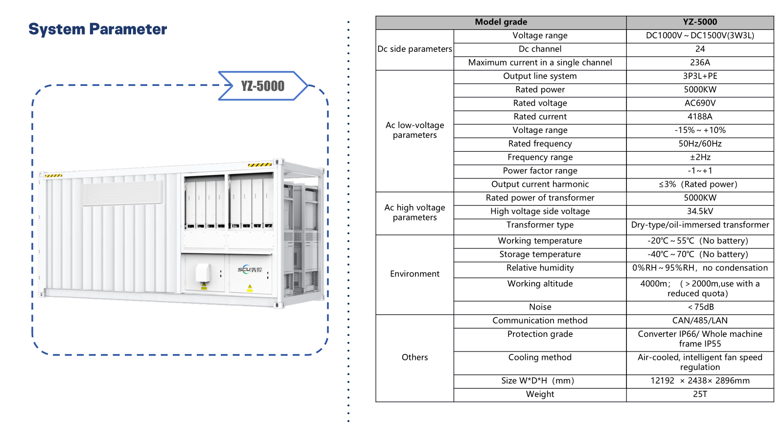 Open full-size product sheet
DC interfaces
- Model
- YZ-5000
- DC voltage range
- 1,000–1,500 V DC (3W3L, as listed)
- DC channels
- 24
- Maximum current per channel
- 236 A
AC low-voltage side
- Rated power
- 5,000 kW
- Output wiring
- 3P3L + PE
- Rated voltage / current
- 690 V AC / 4,188 A
- Voltage operating range
- −15% to +10%
- Rated frequency / range
- 50 Hz or 60 Hz / ±2 Hz
- Power factor range
- −1 to +1 (as listed)
- Output current harmonics
- ≤3% at rated power
Medium-voltage transformer
- High-voltage side
- 34.5 kV
- Transformer rating in supplied sheet
- 5,000 kW; kVA rating to be confirmed
- Transformer type options listed
- Dry-type / oil-immersed; project selection required
Environment and enclosure
- Operating / storage temperature
- −20°C to +55°C / −40°C to +70°C (no battery)
- Relative humidity
- 0–95% RH, non-condensing
- Working altitude
- Up to 4,000 m; derating above 2,000 m
- Noise
- <75 dB; measurement conditions not supplied
- Protection
- Converter IP66 / whole-machine frame IP55
- Cooling
- Air-cooled with intelligent fan-speed regulation
- Communications
- CAN / 485 / LAN
- Dimensions W × D × H
- 12,192 × 2,438 × 2,896 mm
- Weight
- 25 tonnes
Temperature and protection ratings above apply to this substation equipment, not to the BESS battery. Confirm transformer kVA, vector group, impedance, grounding, protection settings, fault duties, communications protocol details and generation/PCS interfaces during engineering. The listed DC channels do not by themselves define the final battery or PCS allocation. Grid-forming, black start and off-grid operation are not established by this sheet.
Explore substation integrationWhat is defined later, in writing
A substation datasheet is not a system design. How storage behaves on your network — including any resilience or backup role — depends on engineered controls, protection and an approved design. It does not automatically replace UPS or generators.
Civil works, installation, commissioning, inland transport, duties and taxes, utility interconnection and permitting or AHJ approvals are separately confirmed scope.
Subject to approved submittals
- Final single-line diagram and protection scheme
- PCS and battery interface definition
- Grid-forming or grid-following operating mode
- Islanding capability, if any
- Duty cycle, usable energy and warranty terms
Get Started
Size your substation count with our engineers
Tell us your target MW, MV system and interconnection status. We will return a project-specific quotation with scope boundaries stated plainly.