Fully immersed module design
Battery cells are fully immersed in cooling fluid, making thermal management an integral part of the module—not just an external cabinet-cooling feature.
Module description · p. 5
Build your data center where the project needs to be—even without a utility connection. Pair on-site turbines and generators with battery energy storage, medium-voltage substations and coordinated controls to create a site-engineered, utility-independent power system for remote compute campuses.
Storage reference only, not a delivered installation. Turbines, generators, fuel systems and microgrid controls are separately engineered and scoped.
Immersion cooling · Thermal management & safety
All BuildingFab battery cell modules use immersion cooling, surrounding the cells with cooling fluid for direct thermal management. Our EP314-1P52S module’s UL 9540A report documents the following safety observations from testing at 100% state of charge.
Source: ANSI/CAN/UL 9540A:2026 module-level report CQES260700094201 · August 11, 2026.
Battery cells are fully immersed in cooling fluid, making thermal management an integral part of the module—not just an external cabinet-cooling feature.
Module description · p. 5
No external flaming or flame extension was observed during the reported module-level thermal-runaway test.
Summary and observations · pp. 3, 18–19
The reported module test recorded no explosion, flying debris, sparks or electrical arcs.
Test observations · p. 18
No additional thermal-runaway events or re-ignition were observed during the report’s post-test monitoring period.
Supplementary observations · p. 19
Results apply to the tested module and conditions, not complete-system certification. Internal cell-to-cell propagation and flammable vent gas occurred during the test; the observations above do not mean zero fire risk.
Full immersion puts cooling fluid in direct contact with the cells. Combined with an engineered enclosure and battery management, this architecture places thermal control at the core of the battery module.
Pair immersion-cooled storage with turbines or generators, UPS and medium-voltage substations for a coordinated data center power solution tailored to your site.
Source: report pp. 4–5, 11. Ratings shown are for the referenced module, not the complete BESS container.
Beyond grid access
For remote sites and campuses where utility service is unavailable, bring-your-own-power means supplying the data center from a dedicated on-site generation fleet. Turbines and generators provide primary energy; BESS and substations integrate that energy into the campus power system. The focus is dependable site power—not utility tariff optimization.
In a grid-connected site, "behind the meter" describes customer-side equipment. Without a utility connection, the more precise term is an off-grid or islanded microgrid. This offering addresses both, with the emphasis on utility-independent operation. Batteries store energy rather than create it: sustained operation still depends on sufficient generation, reliable fuel supply and an approved island-mode design.
What it does
Plan data center power around on-site turbines or generators where utility service is unavailable or a grid connection is not part of the project. Generation capacity, fuel supply and redundancy must support the full campus load.
Turbines and generators supply sustained energy. BESS charges from those sources and can buffer rapid compute-load changes or support generator transitions within its approved power, energy and response limits.
Coordinate generation, battery PCS, medium-voltage substations, site distribution and UPS through an engineered microgrid control and protection scheme. Island operation requires a qualified voltage and frequency reference, not just installed batteries.
Continuous operation is a system-level design requirement. Generation adequacy, fuel resilience, maintenance coverage and battery operating limits must be evaluated together; a BESS capacity rating alone does not establish site autonomy.
Reference architecture
A conceptual utility-independent arrangement: generation and storage connect to a shared site network, with coordinated controls serving the data center. These are system roles, not a finalized series-wiring diagram. Final topology, source interfaces, protection and controls are defined in the approved single-line.
Primary energy supply for a remote campus. Size the generation fleet, fuel infrastructure and reserve capacity around continuous site demand, maintenance and contingency requirements.
2.5 MW / 5 MWh, 20-ft reference battery containers store energy from on-site generation. Two per substation form one repeatable 5 MW / 10 MWh storage block.
Each 5 MW / 34.5 kV reference substation connects two BESS units to the site network. Generation interfaces, grounding and distribution voltages require project-specific engineering.
Coordinate source dispatch and power delivery to critical compute and cooling loads. Island stability, load shedding, black start and UPS coordination must be specified and validated in the approved design.
Each 20-ft BESS container is described as a liquid-immersion lithium battery with busbar cabinet, liquid cooling and fire suppression. UPS, BESS and substation production lead time is 12–16 weeks, plus 4–8 weeks for shipping. Expediting options are available. These timings apply to the equipment, not installation and commissioning of a complete generation plant. The nominal two-hour storage duration is not the campus operating autonomy with generation running.
Product technical detail
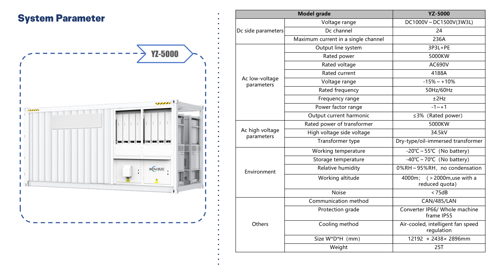
The supplied system sheet identifies DC channels, a 690 V AC low-voltage side and a 34.5 kV transformer interface. These details support coordination of the battery/conversion equipment with the site medium-voltage network. For the reference project, one substation connects two 2.5 MW / 5 MWh BESS units.
 Open full-size product sheet
Temperature and protection ratings above apply to this substation equipment, not to the BESS battery. Confirm transformer kVA, vector group, impedance, grounding, protection settings, fault duties, communications protocol details and generation/PCS interfaces during engineering. The listed DC channels do not by themselves define the final battery or PCS allocation. Grid-forming, black start and off-grid operation are not established by this sheet.
Explore substation integrationContainerized battery storage
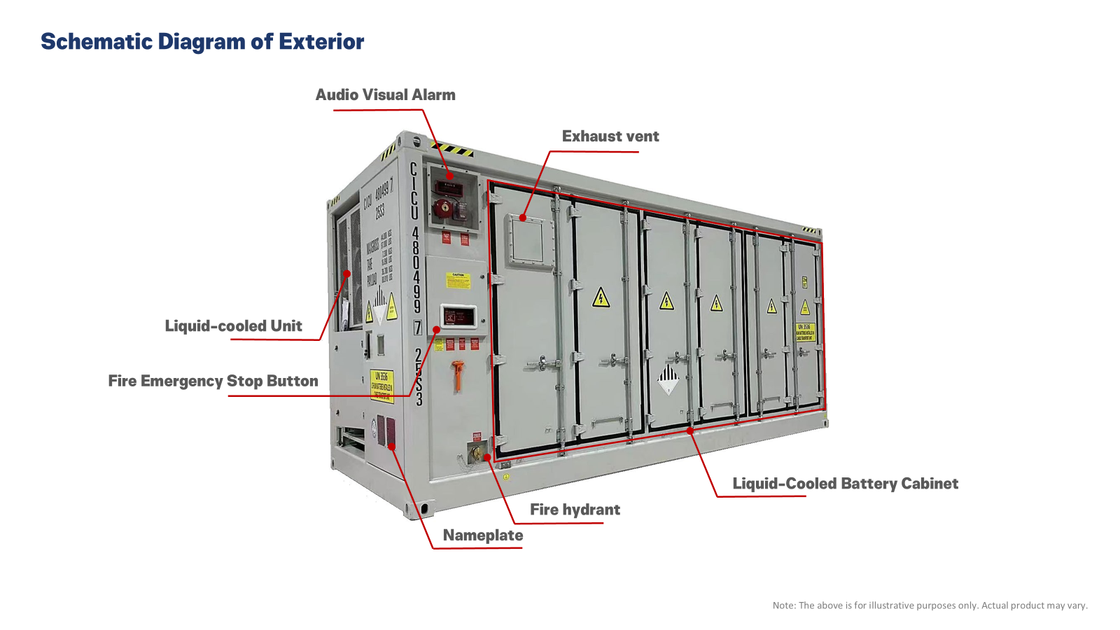
For the BTM reference configuration, each 20-ft storage unit is specified at 2.5 MW / 5 MWh, with a busbar cabinet, immersion-cooled battery cell modules, liquid cooling and fire suppression. Two units form a 5 MW / 10 MWh storage block connected through one 34.5 kV substation. The supplied exterior illustration identifies the equipment interfaces to coordinate during site design; exact model matching requires an approved submittal.
 Open full-size exterior drawing
BuildingFab’s battery cell modules use full-immersion fluid cooling for direct thermal management at the cell level.
The exterior drawing identifies a liquid-cooling unit and exhaust vent. Maintain engineered access and ventilation clearances; heat rejection and auxiliary loads require confirmation.
A local audio-visual alarm provides a visible and audible indication. Alarm logic, remote signals and microgrid integration are defined during engineering.
The exterior includes a labeled fire emergency-stop button. Shutdown actions and coordination with generation, PCS and site protection require an approved cause-and-effect sequence.
The drawing labels a connection as “Fire hydrant.” Suppression agent, detection, water requirements and site fire interfaces must be confirmed with the manufacturer and AHJ.
A labeled nameplate and cabinet access doors support equipment identification and servicing. Confirm final model, ratings, lifting requirements and maintenance clearances before installation.
Sixteen reference BESS units total 40 MW / 80 MWh, paired with eight 5 MW substations. Nominal duration is two hours at full power before losses and operating limits—not guaranteed usable runtime. Turbines or generators provide sustained energy for remote campuses; BESS stores that energy and supports load changes within approved response limits. The EP314-1P52S module report provides model-specific LFP cell and immersion-cooling data. We tailor module selection, DC configuration, thermal management and usable energy to your site’s power requirements and selected container configuration.
A turbine-led plant can supply sustained site demand, while a generator fleet can serve as primary, reserve or backup generation according to the design. BESS can help manage rapid AI load changes and support source transitions, subject to validated PCS response, power headroom and available stored energy.
Operating without a utility requires an engineered voltage and frequency reference, coordinated dispatch and protection, plus fuel and maintenance provisions. Black start, island operation and interruption performance are specified and validated—not assumed from the battery quote. UPS remains part of the critical power chain where required; storage does not automatically replace it or the generation fleet.
Qualification
Projected compute and cooling load, peak demand, ramp rates and campus growth phases
Turbine or generator type, ratings, fuel availability, delivery logistics and maintenance plan
Required redundancy, operating autonomy, reserve margin and acceptable interruption limits
Available pad area, access routes and site conditions for 20-ft and 40-ft containers
Single-line diagram, UPS topology, island-mode controls, emissions permits and AHJ requirements
Who owns civil works, installation, commissioning and inland transport
Turbines, generators, fuel infrastructure, generation balance of plant, microgrid controls, civil works, installation, commissioning, inland transport, duties and taxes, emissions permitting and AHJ approvals require separately confirmed scope. Utility interconnection applies only if a grid connection is part of the project. Pricing is provided as a project-specific quotation.
Get Started
Share your remote location, target campus MW, turbine or generator plans, fuel supply and uptime requirements. Discuss a coordinated BESS and substation solution with clearly defined generation and integration scope.